After all the modifications I did to FC, OSD, PDB it was time to do a test flight.
sadly I do not have a complete drone frame available at the moment. So I grabbed some parts from other frames and drones lying around and build something that should be able fly.
Current setup for this maiden testflight: 1806 2300kv motor with 4 inch props on 3cell. This should produce just enough lift to hover.
And yes the Oversky MUL-A is flying. It needs to be tuned, but I'm not going to spend time on tuning this setup as this is just a test setup. Now I have to make or buy a suitable frame for this flightcontroller.
Showing posts with label mul-a. Show all posts
Showing posts with label mul-a. Show all posts
Friday, March 15, 2024

Tuesday, March 12, 2024
Oversky MUL-A PDB fix
BEWARE! execute at own RISK, this is a DIY project, no warranty. :)
Oversky does not give any maximum power or amperage rating for PDB (power distribution board) that is shipped with the MUL-A flight controller. Oversky mentions that this board is not compatible with motors lager then 2203. But that doesn't tell anything about the maximum power or current. E.g: a 1806 motor on 4 cell with 4 inch props can draw more current then a 2203 motor on 2 cell with 6 inch prop.
Some problems on the PDB that limit the current.
- the power supply connector. It's even smaller than a XT30 connector. so less than 30 AMPS.
- the solder pads for the motors. These are also very small. I guess less than 8 AMPS per motor.
What I noticed is that one side of the board is almost completely coverd in coperfilm connected to the + on the power connector. The other side of board is also coverd in coperfilm and connected to the - on the power connector.
So step one is to change the power connector. Remove it and solder a XT60 connector or simular to the board.
Step 2 is to enlarge the surface area of the motor solder pads. On one side of the board remove the paint for the + pads. On the other side of the board remove the paint for the - pads.
(see pictures below)
This way you can double the surface area wich increases the save amount of current that can flow trough.


 I'm not givving any max current rating for these modification. I'm not an engineer and this all DIY at your own risk. No warranty!
Currently I'm using this PDB with these modifications in combination with 4 x 1806 motors on 3 cell, drawing 12 amps (per motor) at max load. (= total 48A)
I'm not givving any max current rating for these modification. I'm not an engineer and this all DIY at your own risk. No warranty!
Currently I'm using this PDB with these modifications in combination with 4 x 1806 motors on 3 cell, drawing 12 amps (per motor) at max load. (= total 48A)
Oversky does not give any maximum power or amperage rating for PDB (power distribution board) that is shipped with the MUL-A flight controller. Oversky mentions that this board is not compatible with motors lager then 2203. But that doesn't tell anything about the maximum power or current. E.g: a 1806 motor on 4 cell with 4 inch props can draw more current then a 2203 motor on 2 cell with 6 inch prop.
Some problems on the PDB that limit the current.
- the power supply connector. It's even smaller than a XT30 connector. so less than 30 AMPS.
- the solder pads for the motors. These are also very small. I guess less than 8 AMPS per motor.
What I noticed is that one side of the board is almost completely coverd in coperfilm connected to the + on the power connector. The other side of board is also coverd in coperfilm and connected to the - on the power connector.
So step one is to change the power connector. Remove it and solder a XT60 connector or simular to the board.
Step 2 is to enlarge the surface area of the motor solder pads. On one side of the board remove the paint for the + pads. On the other side of the board remove the paint for the - pads.
(see pictures below)
This way you can double the surface area wich increases the save amount of current that can flow trough.


Tuesday, February 13, 2024
Oversky DSMX receiver tips

Some information on this receiver can be found on the Oversky webpage. The RX module is this one: 7CH RX module.


The DMSX module should be installed with the antenna's to the back. But you will notice that this is almost impossible because the antenna will touch the LED module. You can force the antenna on top op the LED module, but I noticed that the antenne will pop of and disconnect very easily.


Tuesday, December 05, 2023
Oversky MUL A OSD firmware update
BEWARE! execute at own RISK, this is a DIY project, no warranty. :)
The OSD (on screen display) firmware update on the Oversky MUL A board is the second mandatory update you need to do. If you update the FC firmware you need to update the OSD firmware because both firmwares need to be compatible with eachother.
 The FC is shipped with MWOSD version 1.5. This OSD firmware is really outdated, software to configure this OSD firmware is not available for download on the internet. And if you can still find it somewhere it does not run on your WIN10/11.
Beware, updating the OSD firmware is difficult. You need to have some good soldering skills. The problem is that the OSD on the FC can not be upgraded via the USB connection by default. The OSD chip that was chipped and installed on the FC does not have a bootloader. To make the OSD firmware upgradable via USB we need to burn a bootloader to the OSD chip. For this you need ATMEL compatible ISP programmer. A popular and cheap ISP programmer is the Usbasp device. You can buy the usbasp device for several bucks online.
 step one: download and install the Arduino Software.
The OSD on the FC is build on a ATMEL atmega 328p chip. With the Arduino IDE software these chips can be programmed with custom applications and you can also burn a bootloader to the chip. I used Arduino verion 1.8.19 for this project. This works fine. Download ARduino IDE here After the Arduino software is installed launch the arduino application. You can now connect you usbasp device to the computer. In the Arduino menu select TOOLS->PROGRAMMER->USBASP. We also need to set the chip type/model that is used on the FC. In the Arduino menu select TOOLS->BOARD->ARDUINO NANO. (this is the Atmega328p chip)
step two: solder the ISP wires to the FC board
The FC board does not have ISP headers that you can use to connect to the USBASP programmer. But we have some luck. the ISP pins on the OSD chip are traced to some small testpin pads. We can use this pads to solder small wires for the USBASP connection. The OSD chip is located next to the heatsink on the FC board. This is the region where we need to solder the wires. We need to Solder 6 wires. 5V (red), GND (black), RESET (yellow), MISO/MOSI/SCK. The pads are very small and if you do not have specialised soldering tools like me, it is very difficult to make this work. But as you can see for me it worked out well. Up to date I have allready updraged the OSD FW on 3 different FC boards. When you have soldered the 6 wires to the FC board you can connect it to the USBASP programmer.
FIRST UNPLUG the USBASP from your computers USB port!!!
Check the images bellow on how to connect the ISP wires to the USBASP pins.
When you have soldered the 6 wires to the FC board you can connect it to the USBASP programmer.
FIRST UNPLUG the USBASP from your computers USB port!!!
Check the images bellow on how to connect the ISP wires to the USBASP pins.


 Recheck that all wires are connected correctly. If the wires are not connected correctly you can damange the entiry FC board! So check, recheck, check again.
step tree:Burn the bootloader to the OSD chip
If the wires are connected corretly to your USBASP programmer you can connect the USBASP to the USB port on your computer. Now the FC is powered on and some leds might start flashing. Go to the Arduino software. Make sure that USBASP programmer is still selected. Now press the "burn bootloader" via the Arduino menu. Burning the bootloader to the OSD chip will take less than 1 SEC. If it takes longer or if you get any error messages during this process you will need to recheck your wires. Connected correctly? Soldered correctly?
If the bootloader was burned succesfully you can disconect the USBASP from your computer. You can also remove all the ISP wires and soldering from the FC board. As from now the OSD firmware can be updated via the usb port on the FC.
step four:Flash the new OSD firmware
 As from now the OSD firmware can be upgraded like the FC firmware via the usb port on the flight controller. Make sure that the usb switch on the FC board is set to OSD.
Multiple OSD firmwares exist and are available on the internet. the MWOSD is very popular, because it is updated frequently and has a lot of features. The MWOSD firmware is free. But the MWOSD application is not free. So if you want to flash the OSD chip with the MWOSD application you first need to buy this application. But because the MWOSD firmware is free and free to download, we can upgrade the OSD chip without the MWOSD application.
As from now the OSD firmware can be upgraded like the FC firmware via the usb port on the flight controller. Make sure that the usb switch on the FC board is set to OSD.
Multiple OSD firmwares exist and are available on the internet. the MWOSD is very popular, because it is updated frequently and has a lot of features. The MWOSD firmware is free. But the MWOSD application is not free. So if you want to flash the OSD chip with the MWOSD application you first need to buy this application. But because the MWOSD firmware is free and free to download, we can upgrade the OSD chip without the MWOSD application.
you can download the MWOSD GUI application here
you can download the MWOSD firmware source code here
Because we used Cleanflight version 2.2 we need a MWOSD version that is compatible. Download MWOSD firmware v2.0 When you have downloaded the MWOSD v2.0 firmware source code you can open this with the Arduino application. All settings that you can set via de MWOSD GUI application can also be set or hardcoded via the firmware. But you need to know what you are doing.
There are at least 2 mandatory settings to change at the config tab:
- define MINIMOSD
- define CLEANFLIGHT
Click the "verify" button in Arduino. If you have no errors you can connect the flightcontroller via the USB connector to your computer. Via the Arduino menu select the correct COM port. Click the "upload" button in Arduino. The MWOSD is now flashed/uploaded to the OSD chip. Reboot the FC and you are ready to go.


The OSD (on screen display) firmware update on the Oversky MUL A board is the second mandatory update you need to do. If you update the FC firmware you need to update the OSD firmware because both firmwares need to be compatible with eachother.

Beware, updating the OSD firmware is difficult. You need to have some good soldering skills. The problem is that the OSD on the FC can not be upgraded via the USB connection by default. The OSD chip that was chipped and installed on the FC does not have a bootloader. To make the OSD firmware upgradable via USB we need to burn a bootloader to the OSD chip. For this you need ATMEL compatible ISP programmer. A popular and cheap ISP programmer is the Usbasp device. You can buy the usbasp device for several bucks online.
The OSD on the FC is build on a ATMEL atmega 328p chip. With the Arduino IDE software these chips can be programmed with custom applications and you can also burn a bootloader to the chip. I used Arduino verion 1.8.19 for this project. This works fine. Download ARduino IDE here After the Arduino software is installed launch the arduino application. You can now connect you usbasp device to the computer. In the Arduino menu select TOOLS->PROGRAMMER->USBASP. We also need to set the chip type/model that is used on the FC. In the Arduino menu select TOOLS->BOARD->ARDUINO NANO. (this is the Atmega328p chip)
step two: solder the ISP wires to the FC board
The FC board does not have ISP headers that you can use to connect to the USBASP programmer. But we have some luck. the ISP pins on the OSD chip are traced to some small testpin pads. We can use this pads to solder small wires for the USBASP connection. The OSD chip is located next to the heatsink on the FC board. This is the region where we need to solder the wires. We need to Solder 6 wires. 5V (red), GND (black), RESET (yellow), MISO/MOSI/SCK. The pads are very small and if you do not have specialised soldering tools like me, it is very difficult to make this work. But as you can see for me it worked out well. Up to date I have allready updraged the OSD FW on 3 different FC boards.


step tree:Burn the bootloader to the OSD chip
If the wires are connected corretly to your USBASP programmer you can connect the USBASP to the USB port on your computer. Now the FC is powered on and some leds might start flashing. Go to the Arduino software. Make sure that USBASP programmer is still selected. Now press the "burn bootloader" via the Arduino menu. Burning the bootloader to the OSD chip will take less than 1 SEC. If it takes longer or if you get any error messages during this process you will need to recheck your wires. Connected correctly? Soldered correctly?
If the bootloader was burned succesfully you can disconect the USBASP from your computer. You can also remove all the ISP wires and soldering from the FC board. As from now the OSD firmware can be updated via the usb port on the FC.
step four:Flash the new OSD firmware

you can download the MWOSD GUI application here
you can download the MWOSD firmware source code here
Because we used Cleanflight version 2.2 we need a MWOSD version that is compatible. Download MWOSD firmware v2.0 When you have downloaded the MWOSD v2.0 firmware source code you can open this with the Arduino application. All settings that you can set via de MWOSD GUI application can also be set or hardcoded via the firmware. But you need to know what you are doing.
There are at least 2 mandatory settings to change at the config tab:
- define MINIMOSD
- define CLEANFLIGHT
Click the "verify" button in Arduino. If you have no errors you can connect the flightcontroller via the USB connector to your computer. Via the Arduino menu select the correct COM port. Click the "upload" button in Arduino. The MWOSD is now flashed/uploaded to the OSD chip. Reboot the FC and you are ready to go.


Sunday, November 05, 2023
Oversky MUL A FC Firmware update
BEWARE! execute at own RISK, this is a DIY project, no warranty. :)
The FC (flight controller) firmware update on the Oversky MUL A board is the first mandatory update you need to do. This is the first and easiest step on getting this FC board to work ano 2023.
The FC is shipped with Cleanflight version 1.12. The PC software (cleanflight configurator) for configuring this CLFL version is depricated and if you can still find it, it will probably not work on your modern operating system (Win 10/11).
step one: download and install the Cleanflight Configurator software on your PC. I tested the version 2.2. You can try a newer version, but v2.2 works on my win 10/11 desktop. you can download this version here
step two: Start the Cleanflight Configurator software. by default the COM1 port wil be selected.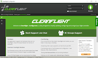
step tree: Connect the FC to your PC via usb.

 make sure to set the switch on the flight controller board to FC.
The board does not need to be conntected to the PDB and the RC module does not need to be plugged in.
Just connect the FC board with an USB cable to your PC.
The leds on the FC board will start to flash and the buzzer will make some beeping noise.
The Cleanflight Configurator on your PC will detect your device and change the COM port.
In my case it's COM3, but on your PC it might be another COM number.
Now hit the connect button. The software will try to connected. It will show you the Cleanflight Firmware version of the FC board. It should be v1.12. The connection will fail because this firmware version is to old.
step four: Flash the new firmware


 click on the firmware tab
select the correct firmware.
- NAZE
- CLFL V2.2.0
(you can try another version at your own risk, but this one is working fine for me)
- click on the "load firmware online" button.
- wait until you see the "online firmware loaded" message
- click on the "flash firmware" button.
- the firmware is now being flashed and verified
- wait until you see the "programming SUCCESFULL" message
- the Flight Controller is now updated with the CLFL V2.2 firmware. This firmware is comatible with the Cleanflight Configurator software. - Now click on the connect button and you can start configuring the FC board. (make sure the FC switch is set to FC and not OSD)
The FC (flight controller) firmware update on the Oversky MUL A board is the first mandatory update you need to do. This is the first and easiest step on getting this FC board to work ano 2023.
The FC is shipped with Cleanflight version 1.12. The PC software (cleanflight configurator) for configuring this CLFL version is depricated and if you can still find it, it will probably not work on your modern operating system (Win 10/11).
step one: download and install the Cleanflight Configurator software on your PC. I tested the version 2.2. You can try a newer version, but v2.2 works on my win 10/11 desktop. you can download this version here
step two: Start the Cleanflight Configurator software. by default the COM1 port wil be selected.

step tree: Connect the FC to your PC via usb.


The board does not need to be conntected to the PDB and the RC module does not need to be plugged in.
Just connect the FC board with an USB cable to your PC.
The leds on the FC board will start to flash and the buzzer will make some beeping noise.
The Cleanflight Configurator on your PC will detect your device and change the COM port.
In my case it's COM3, but on your PC it might be another COM number.
Now hit the connect button. The software will try to connected. It will show you the Cleanflight Firmware version of the FC board. It should be v1.12. The connection will fail because this firmware version is to old.
step four: Flash the new firmware


select the correct firmware.
- NAZE
- CLFL V2.2.0
(you can try another version at your own risk, but this one is working fine for me)
- click on the "load firmware online" button.
- wait until you see the "online firmware loaded" message
- click on the "flash firmware" button.
- the firmware is now being flashed and verified
- wait until you see the "programming SUCCESFULL" message
- the Flight Controller is now updated with the CLFL V2.2 firmware. This firmware is comatible with the Cleanflight Configurator software. - Now click on the connect button and you can start configuring the FC board. (make sure the FC switch is set to FC and not OSD)
Friday, November 03, 2023
hobbyking Oversky MUL A Flight Controller
Hobbyking is currently selling the Oversky MUL A Flight Controller at ridiculous low price.
This FC has everyting onboard and is currently for sale at hobbyking for less then 5$.
But is it worth buying this FC ano 2023? What can you expect from it and what can you do with it.

The specs of the board are very promising.
• CPU FC board : STM32103CBT6
• IMU FC board : MPU6050
• USB,OSD,DCDC power
• 5.8G analog VTX/500mw/32CH/cam supports FatShark goggles
• LED tail lights and Buzzer
• 7 channel DSMX compatible receiver
• Supports outside compass and sonar
• Supports Cleanflight and Baseflight firmware
This board has no MAG and no BARO sensor. This can be a problem if you want to use this board for autopilot missions. But for basic FPV flights these sensors are not needed.
So I bought the board and here is the verdict:
This FC board is worthless unless you are realy into DRONE DIY projects and have some soldering skills. So don't buy it if you need a PNP (plug and play) flight controller for your drone project.
And here is why:
- The FC board, which is NAZE32 compatible, is shipped with Cleanflight version 1.12. This version is outdated and you can't find a working PC software to configure it (ano 2023). You need to upgrade to a more recent version.
- The OSD chip which is minimosd compatible is shipped with MWOSD version 1.5. This version is outdated and you can't find a working PC software to configure it (ano 2023). You need to upgrade to a more recent version.
- The PDB has very small soldering pads to connect the ESC (motor controller). The manual states that brushless motor as from size 2203 are not suported. This is due to the current limition of the PDB caused by the small soldering pads. My guess is that even motors with size 1806 or even 1407 can demand to much current and can damage the soldering pads.
In the next BLOGS I'll provide more information on how to overcome these issues and update this FC so it can be used ano 2023. So after some tuning you will have a working AIO Flight controlle for less than 5$! Be quick before they are soled out.
The Oversky Scisky MUL A Flight Controller is also soled at the website of OverskyRC. The FC manual for this product can also be downloaded from the OverskyRC website.

The specs of the board are very promising.
• CPU FC board : STM32103CBT6
• IMU FC board : MPU6050
• USB,OSD,DCDC power
• 5.8G analog VTX/500mw/32CH/cam supports FatShark goggles
• LED tail lights and Buzzer
• 7 channel DSMX compatible receiver
• Supports outside compass and sonar
• Supports Cleanflight and Baseflight firmware
This board has no MAG and no BARO sensor. This can be a problem if you want to use this board for autopilot missions. But for basic FPV flights these sensors are not needed.
So I bought the board and here is the verdict:
This FC board is worthless unless you are realy into DRONE DIY projects and have some soldering skills. So don't buy it if you need a PNP (plug and play) flight controller for your drone project.
And here is why:
- The FC board, which is NAZE32 compatible, is shipped with Cleanflight version 1.12. This version is outdated and you can't find a working PC software to configure it (ano 2023). You need to upgrade to a more recent version.
- The OSD chip which is minimosd compatible is shipped with MWOSD version 1.5. This version is outdated and you can't find a working PC software to configure it (ano 2023). You need to upgrade to a more recent version.
- The PDB has very small soldering pads to connect the ESC (motor controller). The manual states that brushless motor as from size 2203 are not suported. This is due to the current limition of the PDB caused by the small soldering pads. My guess is that even motors with size 1806 or even 1407 can demand to much current and can damage the soldering pads.
In the next BLOGS I'll provide more information on how to overcome these issues and update this FC so it can be used ano 2023. So after some tuning you will have a working AIO Flight controlle for less than 5$! Be quick before they are soled out.
The Oversky Scisky MUL A Flight Controller is also soled at the website of OverskyRC. The FC manual for this product can also be downloaded from the OverskyRC website.
Subscribe to:
Posts (Atom)